EEG
Definition:
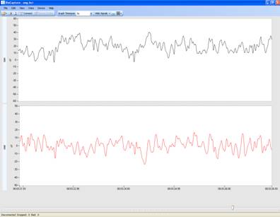
Electroencephalography (EEG) is a biopotential recorded on the surface of the scalp used to examine the electrical activity of neurons firing within the brain.
Amplitude/Frequency:
Range |
Amplitude |
Frequency |
| Alpha |
2-100 ÁV |
8-13 Hz |
| Beta |
5-10 ÁV |
13-22 Hz |
| Delta |
20-100 ÁV |
0.5-4 Hz |
| Theta |
10 ÁV |
4-8 Hz |
| Sleep Spindles |
50-100 ÁV |
6-15 Hz |
| K-Complexes |
100-200 ÁV |
12-14 Hz |
Typical Applications:
Clinically, EEG is used to diagnose brain-related states and diseases such as epilepsy, coma, encephalopathies, and brain death. Experimentally, EEG is often used in research applications such as cognitive psychology, brain computer interfaces, and psychophysiology.
Typical BioRadio Configuration:
The BioCapture software has a Standard Configuration option that provides a pre-set configuration for EEG.
- Select Device Config and then EEG from the drop down menu
- This will automatically set the typical configuration parameters and filter settings.
- Coupling: AC
- Range: ▒750 ÁV.
- Filter: 2nd order, lowpass, Butterworth with upper cutoff of 20 Hz.
Typical Setup:
- Electrodes: Gold cup are typically used for EEG experiments
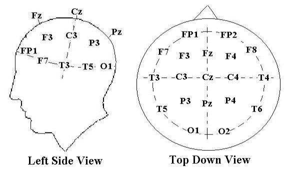
- Electrode Placement: Typically, EEG electrodes are placed based on the 10-20 method.
- The 10 and 20 in the name refer to the percent distances that the electrodes are from each other in proportion to the size of the head.
- It relates the locations on the scalp to the locations of the cerebral cortex.
- The electrode locations used in the 10-20 system are indicated with a letter followed by a number.
- The letters that are used include F, T, C, P, and O, which correspond to frontal, temporal, central, parietal, and occipital, respectively.
- The number in the indicated position corresponds to the left or right side of the head. Even numbers are located on the right hemisphere while odd numbers are on the left.
- Some letters are followed by a Z instead of a number. The Z indicates the midline of the head. The following diagram illustrates these standard electrode positions:

- When placing the electrodes:
Step 1:
Make sure the subject does not have any gel or product in their hair, and participants with shorter hair are more ideal.Step 2:
Part the subjectĺs hair and use an alcohol wipe to prepare the area.Step 3:
Fill the gold cup electrode with electrode conductive gel and wipe it in a small spot on a gauze padStep 4:
Refill the cup and level off the conductive gel so that it is even with the edge of the electrodeStep 5:
Stick the electrode into the conductive gel on the gauze pad with the open end of the cup facing away from the gauze padStep 6:
Take the gauze pad (with the electrode stuck to it) and press it onto the cleaned areaStep 7:
If necessary, place a piece of tape firmly over the gauze pad to create a tight seal to the subjectĺs scalpStep 8:
The ground should be placed on the mastoid process (the bony location behind the ear)
Common Questions:
Q: Why are there occasional spikes in my signal?
A:
This form of noise may be caused by the subject blinking their eyes. Try applying a low-pass filter to the signal to remove this artifact.
Q: Why is there motion artifact in my signal?
A:
Motion artifacts are caused by poor skin/electrode contact or motion of the leads. To reduce the poor skin/electrode contact, see Typical Setup for tips about how to prepare the scalp and attach the gold cup electrode to it. If motion of the leads is causing the noise you should braid or twist the leads together and secure them so that they are not moving as much.
Q: What other types of artifact might appear in my signal?
A:
EMG artifacts can happen if the subject is contracting large muscles close to the electrode sites. Whether it is blinking, chewing, or moving the face, you may pick up EMG-related noise. To prevent this, instruct the subject to relax their face and neck muscles and to keep their eyes as still as possible. This will help reduce the possibility of EMG signals being picked up by the gold cup electrodes.


